We have developed a case study of a Hybrid Braking System (HBS) to illustrate some of the features of the HiP-HOPS technique.
HBS Overview
The HBS is meant for electrical vehicle integration, specifically for architectures that consider one electrical motor per wheel. It is a brake-by-wire system as it does not contain a hydraulic link between the brake pedal and individual wheel-braking actuators; instead it includes an electronic redundant bus system that allows for central and local-wheel control units to communicate.
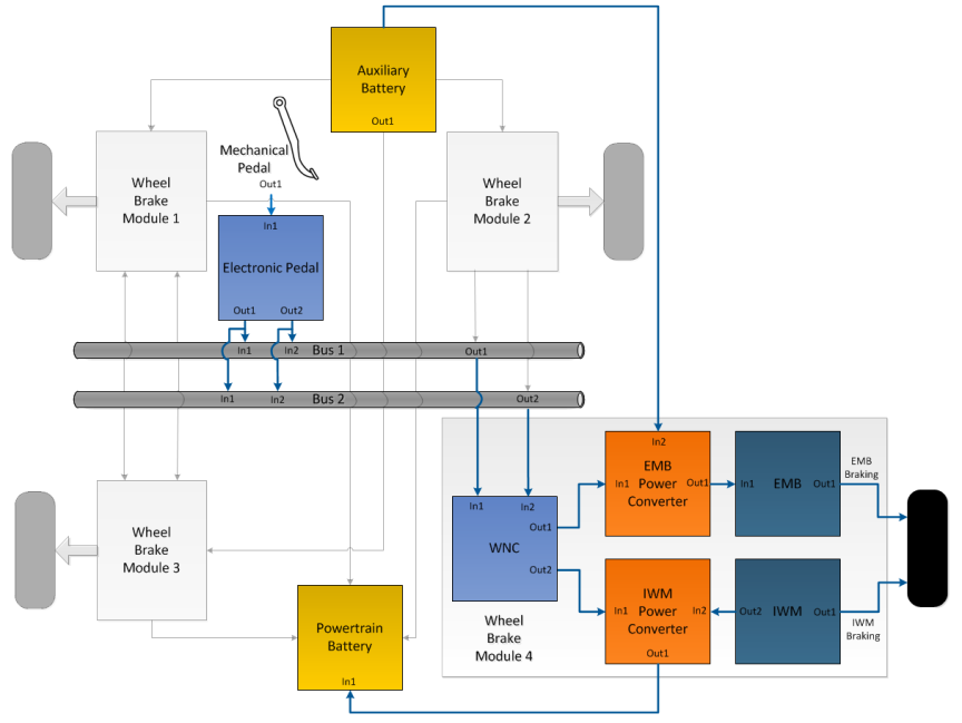 Fig. 1 - HBS Overview
The system is termed “hybrid” as braking is assured by the cooperative effort of frictional Electromechanical Brakes (EMBs) and the In-Wheel Motors (IWMs) from the propulsion architecture. The use of the IWMs to brake gives one of the most interesting features of the HBS: while braking these electrical machines work as generators, transforming the kinetic energy from the wheels into electrical power that is fed to the vehicle’s powertrain battery; the result is in an increase of the vehicle’s range.
HBS Communications and Control
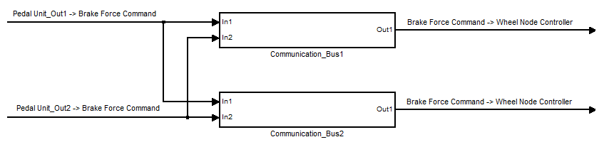
Understanding the communication and control architectures is crucial to be able to acknowledge the HBS failure behaviour. The first thing to note is that communications are mounted on top of the Time-Triggered Protocol for safety-critical distributed real-time control systems (TTP/C). In TTP/C every element that uses the communication system is allocated with a pre-defined slot of time to transmit.
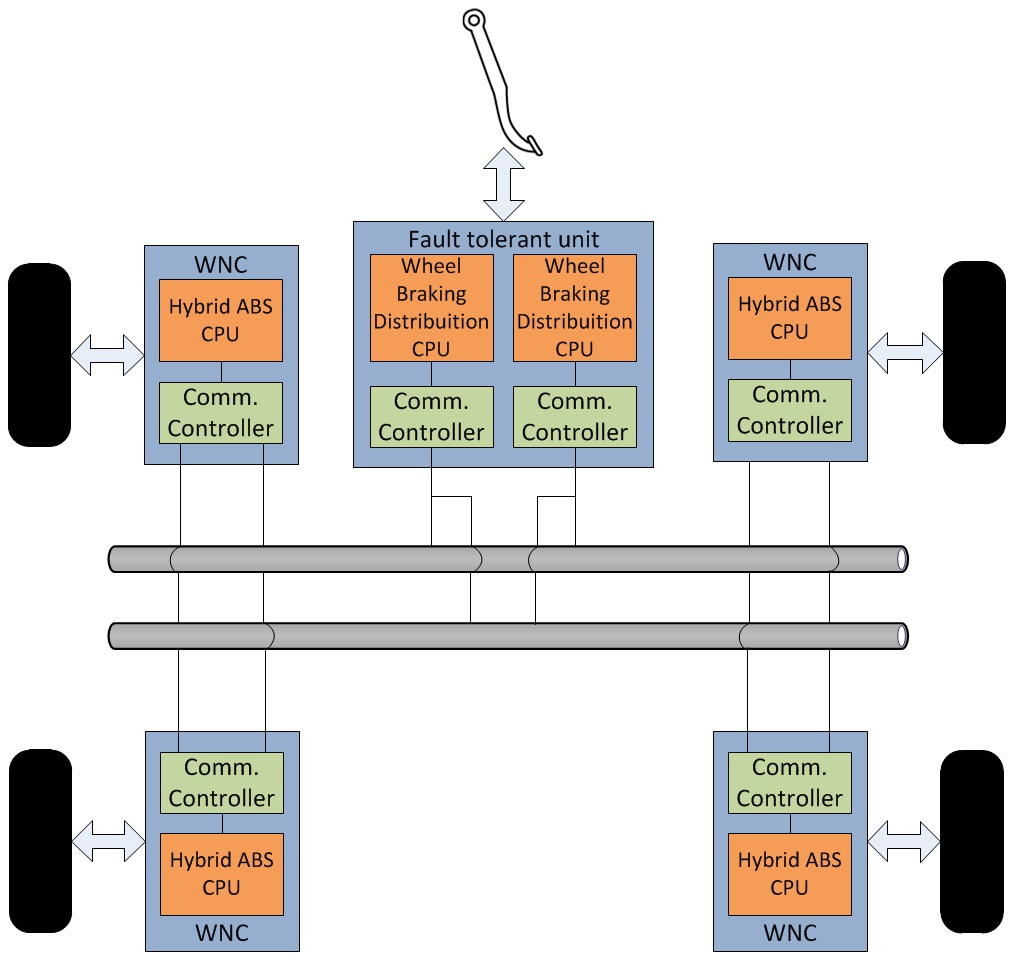 Fig. 2 - HBS Communication and Control Architecture
The HBS includes a central control unit and four wheel processing nodes. In the central control unit, it is calculated the amount of braking force to be applied to each of the vehicle’s wheels. This information is used to compute the braking torque to be developed by each of the actuators in the local Hybrid ABS CPUs.
HBS Model
HiP-HOPS is a flexible tool and it is capable of analysing models developed with Matlab Simulink or ITI Simulation X, for example. A top level HBS model, relating to the early stages of system design, was built using Simulink. For better illustration, the architecture is simplified and only the braking of one wheel is considered in the model presented here.
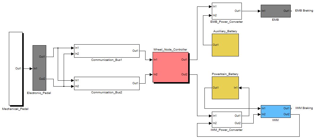 Fig. 3 - HBS Simulink Model
The system behaviour considered in this model is as follows:
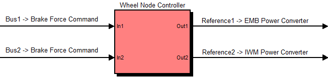
The driver’s action on the mechanical pedal is sensed and processed at the electronic pedal. The latter acts as a central control unit that coordinates 4 local wheel controllers according to the pilot’s braking intentions. All the referred units are interconnected through a digital communication network. After receiving the braking force demand for the wheel it is responsible for, every local unit calculates the amount of torque to be developed by each actuator and then controls them accordingly through power electronics. When braking is taking place, power flows from the low voltage battery (auxiliary battery) to the EMB and from the IWM to the high voltage battery (powertrain battery). The haptic feedback that should be provided to the driver according the braking action is neglected in this model.
HBS Failure Annotations
The next step is to capture in HiP-HOPS the failure behaviour of the HBS architecture, describing how each of its components can fail and also how system hazards are caused by component output deviations; this is done through the use of logical failure annotations .
To better demonstrate how this process should be conducted by the safety engineer, some of the annotations derived for the HBS are introduced in the next sections, starting by the hazards formulations.
Failure Annotations - Hazards
For this simplified case-study, only two hazards were considered:
- No braking after command (H1)
- Wrong value braking (H2)
An omission of braking hazard (H1) occurs when braking is omitted from both the in-wheel motor and the electromechanical brake; a value braking hazard (H2) occurs when either of the two braking devices brakes with an incorrect value. This results in the following failure expressions:
Table 1 - HBS Hazards Annotations
| Hazard | Causes |
|---|---|
| H1 | Omission of EMB.out1 AND Omission of IWM.out1 |
| H2 | Value deviation of EMB.out1 OR Value deviation of IWM.out1 |
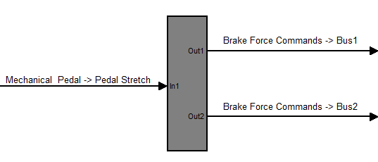
Failure Annotations - Electronic Pedal
For the electronic pedal, it is considered that its two outputs can be value and omission deviated.
-
Omission of the electronic pedal’s outputs can be originated by the omission of the mechanical pedal’s output or by internal components failure detection (expected fail-silent behavior – see here).
-
Internal failures are admitted as a causes of wrong value outputs in spite of the expected fail-silent behavior of this unit. This is because at the considered design stage, details about the electronic pedal internal components are unknown. The same type of output deviation can be triggered by a mechanical pedal deviated output.
Independent internal failures were considered as causes of the deviations of each output of the electronic pedal because the adoption of a redundant structure was expected for this subsystem (see HBS Communications and Control above).
The table below illustrates the fault annotations for the electronic pedal unit.
Table 2 - Failure Annotations - Electronic Pedal
| Output Deviation | Causes |
|---|---|
| Omission-Out1 | OmissionFailure1 OR Omission-In1 |
| Omission-Out2 | OmissionFailure2 OR Omission-In1 |
| Value-Out1 | ValueFailure1 OR Value-In1 |
| Value-Out2 | ValueFailure2 OR Value-In1 |
Failure Annotations - Communication buses
The communication buses are considered to only have internal failures of the omission type due to the TTP/C proprieties: in the presence of other types of faults, such as a value failure caused by EMI interference, a Cyclic Redundancy Check (CRC) mechanism is responsible for discarding the message at the receiving unit, assuring fail-silent behavior. In this way the failure can be classified as of the omission type. Omission of the output of each bus can also be caused by the omission of its two inputs.
Considering the scenario where the electronic pedal produces value deviated outputs, again the behavior of components within TTP/C architectures must be kept in mind: components are expected to deliver correct information or no information at all. Therefore, if a value failure signal is inputted to the bus, the deviation will be propagated. However, as the pedal unit includes two communications controllers, it can be considered that the buses' outputs will only have a value deviation if:
-
the output of the leading controller is value deviated OR
-
the output of the leading controller has an omission deviation and the replica controller outputs a value deviated signal.
Leading controller refers to the element whose information is considered first in the receiving unit. The replica controller information is used when a failure (no information) is detected in the leading element.
Table 3 - Failure Annotations - Communication Buses
| Output Deviation | Causes |
|---|---|
| Omission-Out1 | OmissionFailure1 OR Omission-In1 AND Omission-In2 |
| Value-Out2 | Omission-In1 AND Value-In2 OR Value-In1 |
Failure Annotations - Wheel Node Controller
Both omission and value deviations are admitted for the outputs of the wheel node controller.
-
As with the electronic pedal, in spite of the fail silent expected behavior of the local control unit, at the design stage at hand internal value failures are considered to be possible causes of output value deviations. Moreover, wrong value outputs can also be triggered by value deviation of the output of the leading bus or by the omission of that same output and value deviation of the output of the replica bus.
-
Omission of both outputs can be caused by omission of both buses' outputs. Internal failures can also cause omission of the outputs. These failures may be related with component failure detection which results in the inhibition of the controller.
Like with the pedal unit, independent internal failures were considered for the causes of the deviations of each output. Each power converter reference may be calculated independently to avoid simultaneous failure of both braking devices, for example.
Table 4 - Failure Annotations - Wheel Node Controller
| Output Deviation | Causes |
|---|---|
| Omission-Out1 | Omission-In1 AND Omission-In2 OR OmissionFailure1 |
| Omission-Out2 | Value-In1 OR Omission-In1 AND Value-In2 OR ValueFailure1 |
| Value-Out1 | Omission-In1 AND Omission-In2 OR OmissionFailure2 |
| Value-Out2 | Value-In1 OR Omission-In1 AND Value-In2 OR ValueFailure2 |
HBS and ASILs
One of the features that will be demonstrated in this case study is automatic ASIL allocation and decomposition. It is then necessary to assign each hazard with an ASIL. H1, loss of braking, is assigned ASIL D and H2, wrong value braking, is assigned ASIL A. This was done solely on the basis of the severity of each hazard, as this is an illustrative example. For a ‘real situation’ ISO 26262 risk assessment procedure would be undertaken.
For cost optimisation during ASIL assignement, the user is allowed to define an heuristic that expresses the cost of a component in function of its ASIL implementation. For this case study it was used that agrees with what seems the industry perspective, and that expresses that the highest cost jump is between ASIL B and ASIL C.
Table 5 - ASIL Cost Heuristic
| ASIL | QM | A | B | C | D |
|---|---|---|---|---|---|
| Cost | 0 | 10 | 20 | 40 | 50 |
HBS Fault Tree Analysis Results


HBS Failure Mode and Effects Analysis Results

HBS ASIL Allocation and Decomposition Results

